- 您现在的位置:买卖IC网 > Sheet目录3753 > ATMEGA169P-16MCHR (Atmel)MCU AVR 16KB FLASH 16MHZ 64-VQFN
PIC16F946
DS41265A-page 194
Preliminary
2005 Microchip Technology Inc.
16.3
Power-on Reset
The on-chip POR circuit holds the chip in Reset until
VDD has reached a high enough level for proper
operation. To take advantage of the POR, simply
connect the MCLR pin through a resistor to VDD. This
will eliminate external RC components usually needed
to create Power-on Reset. A maximum rise time for
cations” for details. If the BOR is enabled, the maxi-
mum rise time specification does not apply. The BOR
circuitry will keep the device in Reset until VDD reaches
VBOR
(see
(BOR)”).
When the device starts normal operation (exits the
Reset condition), device operating parameters (i.e.,
voltage, frequency, temperature, etc.) must be met to
ensure operation. If these conditions are not met, the
device must be held in Reset until the operating
conditions are met.
For additional information, refer to Application Note
AN607, “Power-up Trouble Shooting” (DS00607).
16.3.1
MCLR
PIC16F946 has a noise filter in the MCLR Reset path.
The filter will detect and ignore small pulses.
It should be noted that a WDT Reset does not drive
MCLR pin low.
The behavior of the ESD protection on the MCLR pin
has been altered from early devices of this family.
Voltages applied to the pin that exceed its specification
can result in both MCLR Resets and excessive current
beyond the device specification during the ESD event.
For this reason, Microchip recommends that the MCLR
pin no longer be tied directly to VDD. The use of an RC
network, as shown in Figure 16-2, is suggested.
An internal MCLR option is enabled by clearing the
MCLRE bit in the Configuration Word register. When
cleared, MCLR is internally tied to VDD and an internal
weak pull-up is enabled for the MCLR pin. In-Circuit
Serial Programming is not affected by selecting the
internal MCLR option.
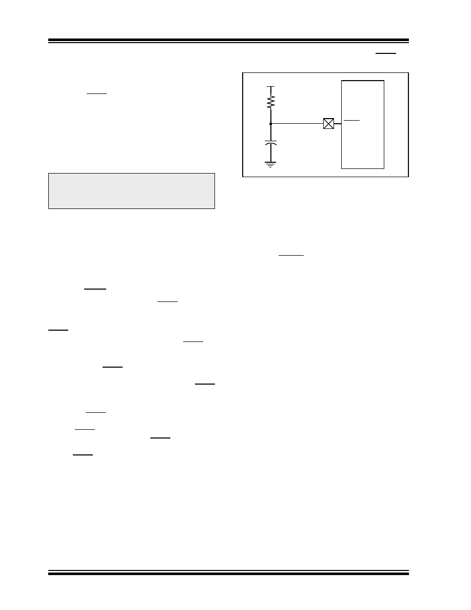
FIGURE 16-2:
RECOMMENDED MCLR
CIRCUIT
16.3.2
POWER-UP TIMER (PWRT)
The Power-up Timer provides a fixed 64 ms (nominal)
time-out on power-up only, from POR or Brown-out
Reset. The Power-up Timer operates from the 31 kHz
LFINTOSC oscillator. For more information, see
Section 4.4 “Internal Clock Modes”. The chip is kept
in Reset as long as PWRT is active. The PWRT delay
allows the VDD to rise to an acceptable level. A config-
uration bit, PWRTE, can disable (if set) or enable (if
cleared or programmed) the Power-up Timer. The
Power-up Timer should be enabled when Brown-out
Reset is enabled, although it is not required.
The Power-up Timer delay will vary from chip-to-chip
and vary due to:
VDD variation
Temperature variation
Process variation
See
DC
parameters
for
details
Note:
The POR circuit does not produce an
internal Reset when VDD declines. To
re-enable the POR, VDD must reach Vss
for a minimum of 100
μs.
VDD
PIC16F946
MCLR
R1
1k
Ω (or greater)
C1
0.1
μF
(optional, not critical)
发布紧急采购,3分钟左右您将得到回复。
相关PDF资料
2-1546217-0
TERM BLK RCPT 20POS SIDE 5.08MM
1-1546217-9
TERM BLK RCPT 19POS SIDE 5.08MM
1-1546217-8
TERM BLK RCPT 18POS SIDE 5.08MM
1-1546217-7
TERM BLK RCPT 17POS SIDE 5.08MM
1-1546217-6
TERM BLK RCPT 16POS SIDE 5.08MM
1-1546217-5
TERM BLK RCPT 15POS SIDE 5.08MM
1-1546217-4
TERM BLK RCPT 14POS SIDE 5.08MM
1-1546217-3
TERM BLK RCPT 13POS SIDE 5.08MM
相关代理商/技术参数
ATMEGA169P-16MCU
功能描述:8位微控制器 -MCU AVR 16KB, 512B EE 16MHz 1KB SRAM, 5V
RoHS:否 制造商:Silicon Labs 核心:8051 处理器系列:C8051F39x 数据总线宽度:8 bit 最大时钟频率:50 MHz 程序存储器大小:16 KB 数据 RAM 大小:1 KB 片上 ADC:Yes 工作电源电压:1.8 V to 3.6 V 工作温度范围:- 40 C to + 105 C 封装 / 箱体:QFN-20 安装风格:SMD/SMT
ATMEGA169P-16MU
功能描述:8位微控制器 -MCU AVR 16K FLASH 512B EE 1K SRAM LCD ADC RoHS:否 制造商:Silicon Labs 核心:8051 处理器系列:C8051F39x 数据总线宽度:8 bit 最大时钟频率:50 MHz 程序存储器大小:16 KB 数据 RAM 大小:1 KB 片上 ADC:Yes 工作电源电压:1.8 V to 3.6 V 工作温度范围:- 40 C to + 105 C 封装 / 箱体:QFN-20 安装风格:SMD/SMT
ATMEGA169P-16MU SL383
制造商:Atmel Corporation 功能描述:MCU 8BIT ATMEGA RISC 16KB FLASH 3.3V/5V 64PIN MLF - Tape and Reel
ATMEGA169P-16MUR
功能描述:8位微控制器 -MCU AVR LCD 16KB FLSH EE 512B 1KB SRAM-16MHZ RoHS:否 制造商:Silicon Labs 核心:8051 处理器系列:C8051F39x 数据总线宽度:8 bit 最大时钟频率:50 MHz 程序存储器大小:16 KB 数据 RAM 大小:1 KB 片上 ADC:Yes 工作电源电压:1.8 V to 3.6 V 工作温度范围:- 40 C to + 105 C 封装 / 箱体:QFN-20 安装风格:SMD/SMT
ATMEGA169P-8AU
制造商:ATMEL 制造商全称:ATMEL Corporation 功能描述:Microcontroller with 16K Bytes In-System Programmable Flash
ATMEGA169P-8MU
制造商:ATMEL 制造商全称:ATMEL Corporation 功能描述:Microcontroller with 16K Bytes In-System Programmable Flash
ATMEGA169PA
制造商:ATMEL 制造商全称:ATMEL Corporation 功能描述:8-bit Microcontroller with 16K Bytes In-System Programmable Flash
ATMEGA169PA_1
制造商:ATMEL 制造商全称:ATMEL Corporation 功能描述:High Endurance Non-volatile Memory segments